How to Install a Bluetooth Kill Switch: Anti-Theft Battery Disconnect Guide
, by iFJF Direct, 10 min reading time
, by iFJF Direct, 10 min reading time

Install a Bluetooth kill switch on your car, truck, or RV in under an hour. Step-by-step wiring guide with torque specs, safety tips, and professional installation best practices.
Installing a Bluetooth kill switch is one of the highest-impact upgrades you can do in an afternoon — and it requires no special tools or advanced skills. In about an hour, you'll have remote battery control from your phone, zero parasitic drain while parked, and a vehicle that physically cannot be started without your permission.
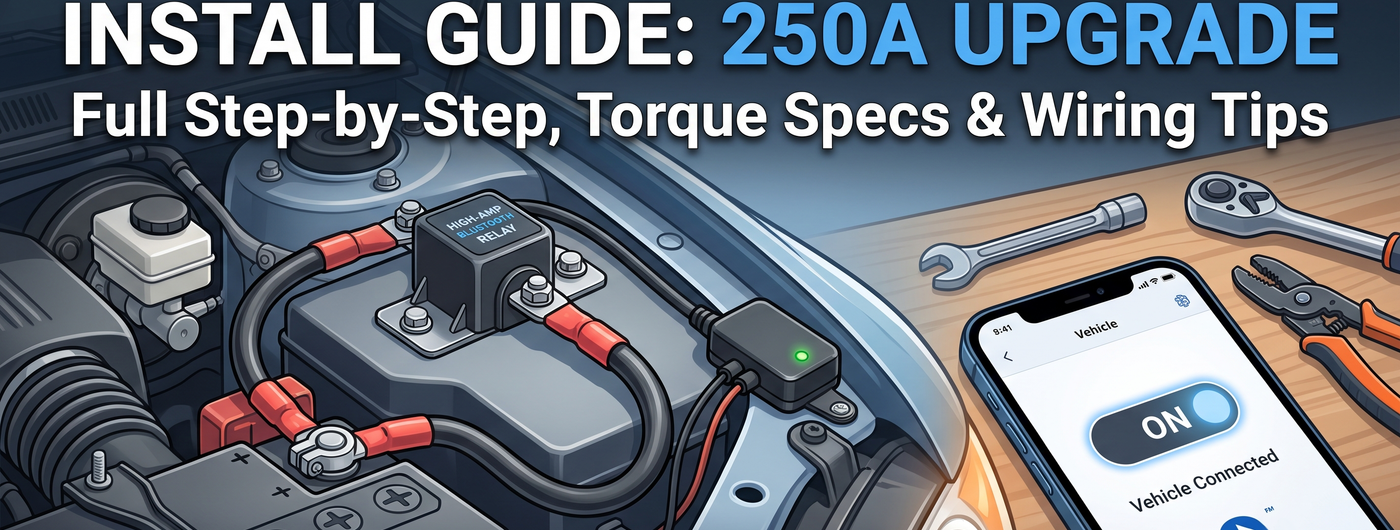
This guide covers the complete installation process for a 250A Bluetooth kill switch on a car, truck, RV, or UTV. We'll go step by step with torque specs, wire routing tips, and the mistakes to avoid.
| Tool / Material | Purpose |
|---|---|
| 10mm socket + ratchet | Battery terminal nuts, mounting bolts |
| 13mm socket | Relay mounting bracket (varies by vehicle) |
| Wire crimper / stripper | Crimping ring terminals on power cables |
| 4-gauge ring terminals (2 pcs) | If cables need resizing for your battery |
| Heat shrink tubing | Weatherproofing crimp connections |
| Zip ties (8-10 pcs, 8" black) | Securing wires along the frame/body |
| Dielectric grease | Battery terminal anti-corrosion |
| Wire brush or terminal cleaner | Clean battery terminals before reconnection |
| Multimeter (optional) | Verify voltage, check for shorts before connecting |
| Drill + 1/4" bit (possibly) | Mounting holes for relay bracket (if no existing holes) |
Always disconnect the negative (-) terminal first, then the positive (+). This order matters: if your wrench touches the chassis while loosening the positive terminal with the negative still connected, you create a dead short — sparks, melted wrenches, and potentially an exploding battery.
The relay is the heavy-duty switch that physically connects and disconnects the battery. It needs to be mounted securely, close to the battery, in a location that stays relatively dry.
Good mounting locations:
Bad mounting locations:
Use the included stainless steel bolts or self-tapping screws. The relay should be solid — it can't rattle around. If drilling is required, check the other side of the panel for wires, hoses, and brake lines before you drill.
This is the main electrical work. There are three power connections:
The relay has two large studs, usually marked "IN" (or "BAT") and "OUT" (or "LOAD"). Connect the battery positive cable to IN, and the vehicle's main power cable to OUT.
If the included cables don't reach, extend them with matching-gauge (4 AWG) cable. Do not use thinner wire — undersized cables create resistance, heat up under load, and can melt insulation or cause a fire.
Torque on the relay stud nuts: 8–10 ft-lbs. Over-tightening strips the stud threads; under-tightening creates a high-resistance connection that heats up.
The control module is the Bluetooth receiver and relay driver. It connects to the relay with two thin wires (typically 16-18 gauge):
Follow the wiring diagram in your kit. The control wires carry milliamps — no special gauge required. Crimp the provided spade connectors onto the module wires and slide them onto the relay coil terminals.
Proper wire routing is what separates a professional install from a hack job:
The control module should be mounted in a dry, accessible location. Good options:
While the module is weather-resistant, keeping it inside the cabin extends its life and improves Bluetooth range (less metal between the module and your phone). Use zip ties or the included mounting bracket to secure it.
If nothing happens when you tap the button:
1. The fuse question: If your kit doesn't include an inline fuse on the main power cable, add one. A 300A ANL fuse within 12 inches of the battery positive terminal protects against a dead short if the power cable gets pinched or chafed. $10 in parts, priceless in fire prevention.
2. Label your work: Use a label maker or paint pen to mark "KILL SWITCH — BYPASS AT RELAY" on the battery cover or fuse box lid. If you sell the vehicle or a mechanic works on it, they'll know what's installed and how to bypass it.
3. Test with accessories on: Turn on the headlights, blower fan, and radio before hitting the kill switch OFF button. If the relay is undersized or the wiring is marginal, the load will expose it immediately. The relay should handle this without any clicking, buzzing, or voltage sag.
4. The first hot day test: After installation, park the vehicle in direct sun on a 90°F+ day and test the kill switch. Heat increases resistance in every electrical connection, and a marginal crimp or loose terminal that works fine at 70°F may fail at 100°F. Better to find out in your driveway than at a trailhead.
| Problem | Likely Cause | Fix |
|---|---|---|
| Relay clicks rapidly (buzzing) | Low voltage at relay coil or weak ground | Check control wire connections; verify battery voltage >11.5V |
| Phone won't pair with module | Module not powered or too far away | Verify module LED is on; move phone within 5 ft; restart app |
| Engine cranks slowly with kill switch ON | High resistance in power connections | Check torque on relay stud nuts; verify cable gauge is adequate |
| Kill switch works but radio presets lost each time | Normal — full battery disconnect | Expected behavior. Use ON during daily driving if preserving settings matters |
| Relay gets hot during driving | Undersized relay or poor connections | Check current rating (needs 250A peak for diesel); verify clean, tight connections |
Q: How long does installation take for a first-timer?
A: Plan on 90 minutes. Experienced DIY mechanics can do it in 45 minutes. Add 20 minutes if you need to drill mounting holes.
Q: Do I need any special automotive electrical knowledge?
A: Basic 12V wiring familiarity helps, but the instructions are designed for anyone comfortable with hand tools. If you've replaced a battery or installed a car stereo, you have the skills needed.
Q: What if I need to jump-start the vehicle with the kill switch OFF?
A: You can't — the kill switch physically disconnects the battery from the vehicle. Turn the switch ON via the app, or manually bypass the relay by moving the power cable from the OUT terminal to the IN terminal (temporarily connecting them together).
Q: Will this drain my battery if I leave the vehicle sitting for months?
A: With the kill switch OFF, the battery is physically disconnected — zero drain. With the switch ON and the engine off, the Bluetooth module draws less than 3mA (negligible). Either way, your battery is safe.

250A peak / 125A continuous. AES-128 encrypted Bluetooth. Weather-resistant. Stainless steel hardware. Everything you need in one box — relay, control module, wiring harness, mounting kit, and installation guide.
45-90 minute install. Ships free from our US warehouse. 1-year warranty.
Shop Now →